TW-1CS 2M Transmission Analyzer
Major Features
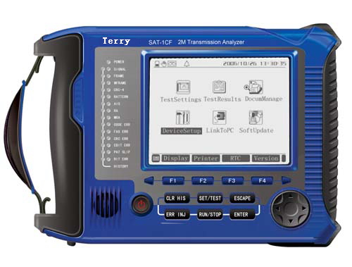
・ LCD large-screen display, 320*240 lattice, backlight, LED indicator
・ Hand held, auto configuration
・ Multi-task operation at one time
・ Store 20 test results and 9 test configurations, with power-off memories
・ PC operation, store, analysis, print
・ Programmable timer
・ Alarm and histogram analysis
・ Software updating
Major Functions
For 2Mbit/s:
・ Service-interrupted error testing
・ Online error testing
・ Framed and unframed signals generating and receiving
・ 2Mbit/s unframed error performance testing
・ 2Mbit/s framed N×64kbit/s channel error testing
・ Bit error, coding error, frame error, CRC error and E bit error testing
・ Signal loss alarm, AIS alarm, framed remote alarm, multi-framed remote alarm, out-of-frame, and pattern loss alarm
・ Frequency offset testing
・ Line signal level and frequency testing
・ Voice channel signal level and frequency testing
・ Pattern slip testing
・ Clock slip testing
・ Straightforward signaling
・ Audio frequency testing
・ Loop circuit delay testing
・ Automatic protection switching time testing (APS)
・ Clock bias function
・ Sound monitoring
・ Duplex 2Mbit/s detecting and monitoring
・ Signal state display. Voice channel content display. Voice channel busy indication
・ Alarm and error histogram analysis
・ Time slot content analysis, drop and insert signal on each time slot
・ Framed content analysis
・ G.703 Template analysis
・ G. 821/G. 826/M. 2100 error analysis
・ Multi error and alarm inserting
・ Three input modes (terminating, bridging and monitoring)
・ Three clock options (internal, external and picking-up)
・ Jitter testing function
・ Touch screen TFT color LCD (optional)
* The functions of yellow fonts description is a module for user to select.
For Datacom:
・ V.24/RS232/V.28, V.35, V.36, X.21, RS-449, RS-485, RS422, EIA-530, EIA-530A datacom testing
・ SYNCH and ASYNCH testing
・ DTE and DCE emulation
・ Bit code testing
・ Pattern slip testing
・ Signal loss alarm
・ Line signal level and frequency testing
・ Loop delay testing
・ Automatic protection switching time testing(APS)
・ G.821, M2100 service interrupt error testing
For co-directional 64Kbit/s:
・ Service interrupt error testing
・ Bit code testing
・ Pattern slip testing
・ Signal loss, AIS alarm
・ Line signal frequency testing
・ Loop delay testing
・ Automatic protection switching time testing(APS)
・ G.821, M.2100 error testing
Technical Index
・ 2Mbit/s Technical Index
(1) Signal input rate: 2048kbit/s ± 100ppm (G.703 requirement±50PPM)
(2) Signal code: HDB3, AMI.
(3) Input jitter tolerance: Up to the requirement of Figure 10.1.
Fig.10.1 Input Jitter Tolerance
(4) Input balance response: attenuation complies with the law of square root of frequency, and is within the range of 0 to 6dB at 1024 kHz.
(5) Input Impedance
(5.1) Unbalance terminating: 75W
Balance terminating: 120W
Reflection loss >18dB within 50Hz~3100kHz
(5.2) Unbalance bridging: >750W
Balance bridging: >1200W
(5.3) Unbalance monitoring: 75W, 26dB gain
Balance monitoring: 120W, 26dB gain
Reflection loss >18dB within 50Hz~3100kHz
(6) Signal structure
(6.1) Unframed structure
(6.2) Framed structure: PCM30, PCM31, PCM30CRC, PCM31CRC
Framed structure complies with the requirement of G. 704
(7) Testing pattern: 26-1, 29-1, 211-1, 215-1, 220-1, 223-1, and artificial code
(8) Impedance of output interface:
(8.1) Unbalance 75W, up to G. 703
(8.2) Balance 120W, up to G. 703
(9) External clock input
(9.1) Signal form: HDB3, NRZ
(9.2) Balance terminating resistance: 120W
Unbalance terminating resistance: 75W
Balance bridging resistance: >1200W
Unbalance bridging resistance: >750W
(10) Error code insertion: None, single, or ratio 10-1~10-7.
・ Co-directional 64k Technical Index
(1) Signal input rate: 64kbit/s ± 100ppm(G.703 requirement±100PPM)
(2) Input impedance: Balance 120W, up to G.703
(3) Input jitter tolerance: Up to G.823.
(4) Impedance of output interface: Balance 120W, up to G.703
(5) Testing pattern: 26-1, 29-1, 211-1, 215-1, 220-1, 223-1, and artificial code
・ Datacom Index
(1) Data interface type: V.24, V.35, V.36, X.21, RS-449, RS-485, EIA-530 and EIA-530A.
(2) Generator
(2.1) SYNCH mode
Clock source: Internal or external clock
Phase relation between clock and data: co-direction or reverse direction.
Rate: 1.2, 2.4, 4.8, 9.6, 14.4, 19.2, 38.4, 48, 56(kbps), N×64kbps (N=1~32)
Error: ±15ppm (ppm: parts per million)
(2.2) ASYNCH mode
Rate: 50,75,110,150,200,300,600,1200,2400,3600,4800,7200,9600; 14.4k,19.2k,38.4k,57.6k(bps)
Data structure: Word length: 5, 6, 7, 8(bits) Stop bit: 1, 2(bits)
Odd-even check: odd, even, 1, 0, none
(2.3) Error code insertion: None, single, or ratio 10-1~10-7.
(3) Receiver
(3.1) SYNCH mode
Clock source: Internal or external clock
Phase relation between receive clock and receive data: Equidirection or reverse direction.
Clock Rate: 2048kbps at a maximum
(3.2) ASYNCH mode
The rate and data are the same as those of the generator.
(4) Testing pattern: 26-1, 29-1, 211-1, 215-1, 220-1, 223-1, and artificial code
Other Parameters
・ Power supply
(1) Special power adapter
Input: AC220V 50Hz
Output: DC 9V 1A
(2) Internal rechargeable battery
4000mAh, 6V nickel-hydrogen rechargeable battery
Working time: 8 hours
Charging: 8 hours at power-off state, and 12 hours at power-on state
・ Dimension and weight
L×W×H: 200×160×42mm
Weight: 950g
・ Ambient parameters
Operation temperature: -10~50℃
Storage Temperature: -30~+70℃
Humidity: 5%~90%, non-condensing
Standard Configuration
|
No. |
Item |
Qty |
|
1 |
TW-1CS 2M Transmission Analyzer |
1 set |
|
Attached files |
|
2 |
User’s manual |
1 pc |
|
3 |
Software disc |
1 pc |
|
Attached accessories |
|
4 |
75Ω Coaxial testing line |
1 pc
根 |
|
5 |
BNC-L9 Testing line
CESHIYI |
2 pcs |
|
6 |
RS232 serial line |
1 pc |
|
7 |
Special testing cable of data communicationⅠ(V.24,RS-485,EIA-530,EIA-530A) |
1 pc |
|
8 |
Special testing cable of data communicationⅡ(RS-449,V . 36)
|
1 pc |
|
9 |
Special testing cable of data communication Ⅲ(X . 21) |
1 pc |
|
10 |
Special testing cable of data communication Ⅳ(V . 35) |
1 pc |
|
11 |
G.703 CO special testing cable(64Kb/s coaxial interface) |
1 pc |
|
12 |
Power adapter |
1 pc |
|
13 |
Data self-loop head |
1 pc |
|
14 |
Switch cable
|
1 pc |
|
15 |
Handy-case |
1 pc |
|
16 |
Serial printing line(optional) □ |
1 pc |